JLNlabs website - the best resource on the web
I am intrigued by the claims of Floyd Sweet and Tom Bearden about this device. I have found several 4"x6"x1" barium ferrite magnets with which I can experiment. I have constructed a equipment to condition the magnets according to information found on the web about this device. The A, B, and C conditioning coils are wound. A high power pulse bank is constructed, with variable output, which is triggered by the waveforms on the conditioing coils.
Many people have experimented with this device, and have found properties
worth further investigation. This project is on temporary hold until
I explore another overunity device (MEG) that may have good promise.
Please excuse the crude drawings, since they are but just a starting point for future experiments. The part values are not critical, as long as the circuit works properly when you build and debug it. Other designs would more efficient, but the low cost of using components I already had on hand was more important.
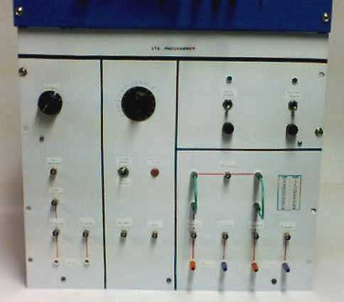
This is a photo of the front of the conditioner panel. Please
excuse the picture quality as I just scanned a polaroid I had in my lab
notebook. It is a 19" rack mount panel, with a homebuilt function
generator at the top. Many BNC connectors were included for test
point monitoring.
The left most portion is the A coil connection area. Thje black
knob in this area is for A coil amplitude control.
The center area is the high voltage pulse bank control section.
The black nob in this area is for variac power contol.
The lower right area is the B coil and C coil connection area.
The upper right area is the input line power area, with fuses and indicating
lights.
VTA Conditioner Front Panel
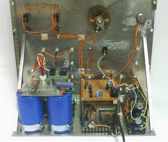
The panel rear area is laid out so everything fit. The two large
capacitors at the lower left are the pulse bank, and support an aluminum
plate and pulse SCR. Mounted on standoffs is the control circuit
board. Under the circuit board is the 450 vac transformer.
The low voltage power supply for the circuit board is at the lower right.
At the upper center is the variac control for the 450 vac transformer.
VTA Conditioner rear view
The first coil wound around the perimeter of the BaFe magnet is the
A coil. It is fed with a 60 HZ sine wave in the range of 70 watts
of power. I used a sine wave generator to feed the panel, and is
split into two signal paths. One portion feeds teh control circuit
board for pulse synchronization. The other part is fed to a 100 watt
audio amplifier that feeds intot he A coil. The amplitude of the
sine wave is control by a simple potentiometer. I added BNC test
points so I could moniotr the voltage and current of the A coil waveform.
The current sample resistor is a copper bar calibrated at 50 mv drop when
15 amps passes thorugh it. Other sampling resistors could just as
easily be used.
A coil connections
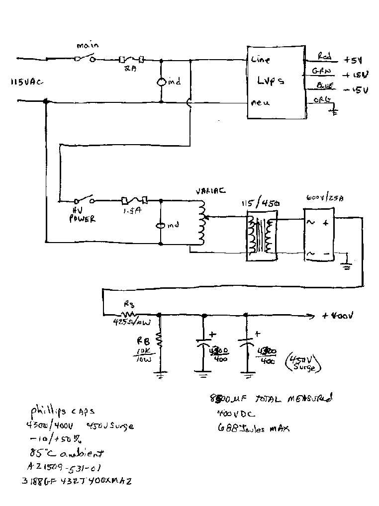
Synchonized with the peak of the supplied AC since wave on the A coil,
a high power pulse is supplied to one of the coils around the magnet.
The number of joules of energy in the pulse may be critical, so the voltage
on the capacitor pulse bank wqs made adjustable. I used a small variac
on the input of the 450 VAC transformer, and limited the charge rate into
the capacitors with a 425 ohm/10watt resistor. The capacitors are
surplus 4300 uf/400 vdc units connected in parallel. Rb is a bleeder
resistor so the capacitors slowly discharge when not being used.
The LVPS (low voltage power supply) in the upper right is used to power
the control circuit board.
Variable pulse bank power supply
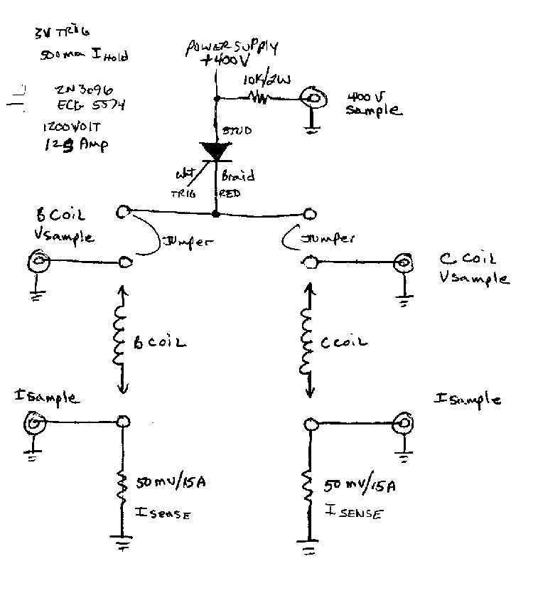
The pulse bank is fed through an SCR to the B, or C coils when triggered
by the control board. Jumpers and test points are available to change
configurations as future experiments require. The test points are
BNC connectors to be connected to an oscilliscope wor waveform monitoring.
The current sense resistors (50 mv / 15a) are calibrated copper bars which
produce a known voltage drop for a specified current passing through them.
The stud mounted SCR is rated at 125 amps.
B/C coil connections
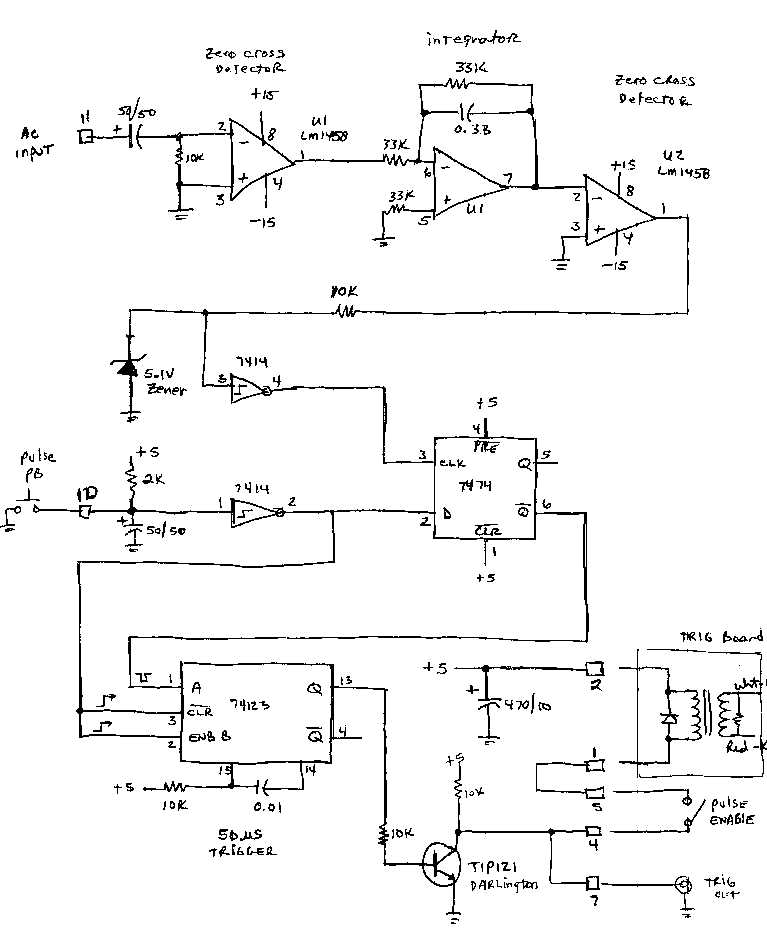
The control boards main function is to sample the 60 hz since wave being
fed to the A coil, find the peak of hte waveform, and to create a trigger
pulse to the SCR when commanded to do so. Since 60 Hz is the operating
frequency I desire, some tuning of the circuit components was needed to
get proper timing. The zero crossing detctors andintegrator find
the peak ofhte AC waveform. A 7414 schmidt trigger clean up the analog
voltage to a nice digital signal. When the front panel pushbutton
is depressed, the 74123 monostable creates a single trigger pulse to the
SCR through a driver transistor and trigger transformer. I added
an SCR trigger test point so I could trigger the scope for waveform moniotring.
The pulse enable switch is used so an errant pulse discharge would not
be created useful when powering down the equipment. The active components
were selected from what I had on hand.
Control Board Schematic