Motionless Electromagnetic
Generator
Send me an email at
mbauer@execpc.com Last update 12/30/00
QUICK LINKS:
MEG replication efforts by JLNlabs
MEG relication efforts by Svein Utne
12/7/00
The core material I am using for my replication is a ferrite
from FROST.
ATC-FROST
choke cores
The cross sectional area is approximately 1 inch by 1 1/8 inches.
The magnet is a stack of rare earth grade 27 NIB magnets from
Edmund Scientific.
Edmund
Scientific
Many different primary and secondary windings have been wound
with various turn ratios. Experiments have been performed
using different combinations of windings, magnet orientations,
load resistances, drive pulse timing and frequency, and drive
voltage. Waveforms are monitored with several Tektronix
oscilloscopes. Input power is monitored with digital
volt/ammeters.
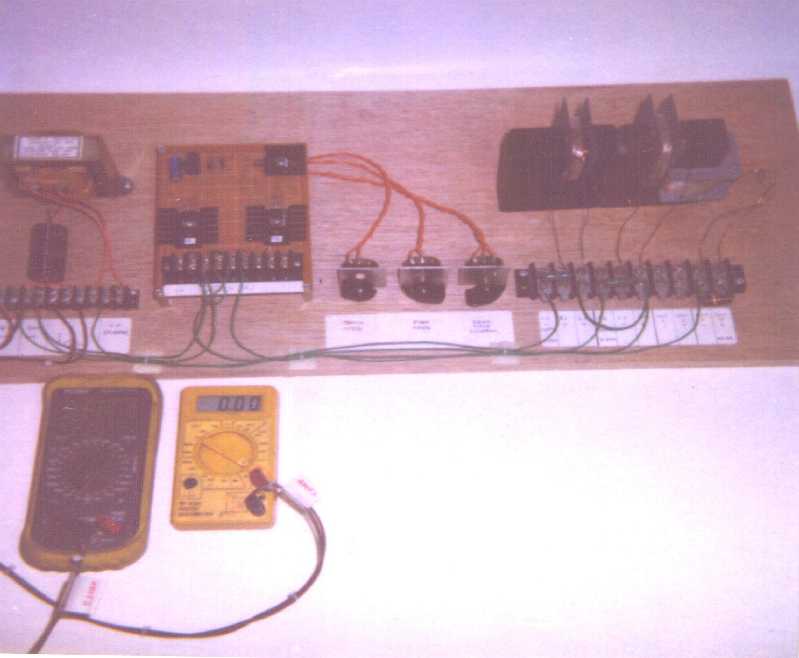
Photo of experimental breadboard
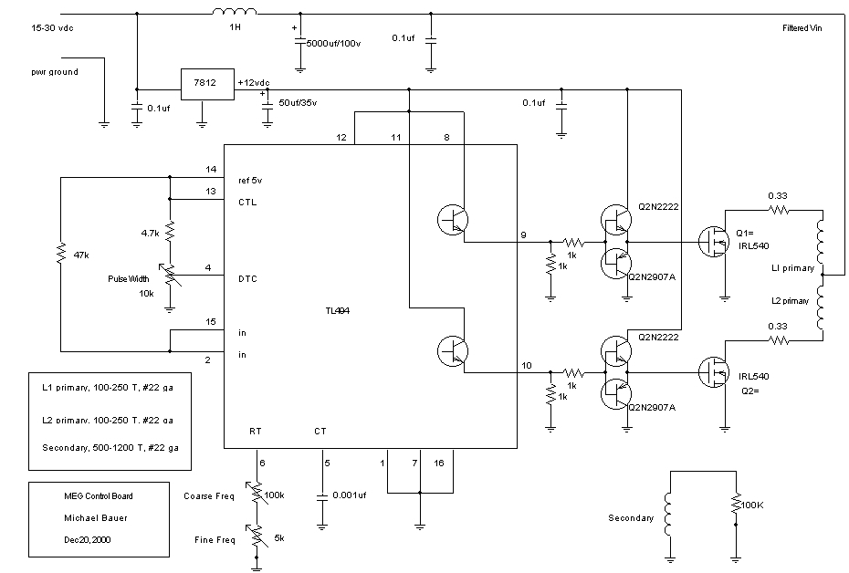
The control board is a close copy of the control circuit
offered by J Naudin on his website. Several changes were
incorporated for variable dead time control and different Mosfet
driver transistors. Components are available from Digikey.com More
circuit changes are forthcoming to fix the exponential decay of
the drive voltage at the input of the Mosfet drivers.
Currently, the TL494 PWM generator chip is not configured for
active pulldown of the gate input of the Mosfet. With a
Ciss of 1800 pf for the IRL540 Mosfets, and a pull down
resistance of 1Kohm, a delay of several microseconds occurs
between the PWM pulse turnoff and the Mosfet turnoff. By
using the variable dead time control of the PWM chip, correct
pulse width can be obtained, but that is only a temporary fix.
Schematic of original control board
The optimum configuration I have been able to obtain is 1200 Vpp output across a 100 Kohm resistive load. The output voltage is a pure sine wave. The primary is 100 turns, and a single secondary of 500 turns. Power supply input is 25.0 Vdc @ 130 Ma., not including the control board power. Operating frequency is 55 Khz, with minimum dead time control. This is without magnets in the core.
Power input is 3.25 watts. Output power is calculated at 1.80 watts. Efficiency is therefore 55%. No overunity seen yet.
Yes, an unloaded secondary produces several thousand volts and arcs over in the windings. This has been verified.
When magnets are added, slightly higher output voltage is obtained in one orientation, and slightly less output in the other orientation. Still no overunity seen. Efficiency still below 100%.
Price quotes for Metglas cores used by several replication
efforts can be found at Eastern Components. The latest
prices quoted for the AMCC-320 Honeywell metglas core is $162.00
US. The AMCC-125 core is $87.25 US. Single
quantity, shipping extra. Off the shelf cores.
Eastern components
I will utilize the present ferrite cores I have to explore the theories proposed, and to develop procedures for constructing a newer version.
12/9/00
New information from J Naudin about cross flux switching of
the permanent magnet.
Cross flux
switching from JLNlabs
I am in the process of changing my design to incorporate the cross flux primary switch. I will try using a silicon steel transformer core as a starting point. The core was cut on a milling machine to fit across the ferrite core I am using. I'll try various winding configurations to optimize the performance.
12/12/00
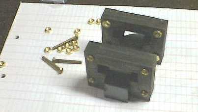
I used a high speed cutoff wheel to cut the silicon steel core to the rough shape to fit over the ferrite core I am using. Brass hardware is used to hold the stack of plates together for finishing. Then, using a bench grinder, I was able to slowly widen the gap to fit snugly over the ferrite core. Here, I am using a scrap piece of ferrite as a width gauge during final grinding.
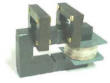
In this picture, here's how the bare cross flux cores fit over the ferrite cores. Note, the ferrite is very brittle and corners break off easily. These ferrite cores are only being used for show.
As a starting point for testing, I am using 250 turns of #22 gauge wire on each cross flux primary. This secondary coil only has 500 turns. Future experiments will use one of my other secondaries previously wound with more turns from other test runs.
12/16/00
The cross flux principle seems to be a dead end for me at the moment. I did prove that the cross flux method almost got rid of the inductive coupling between primary and secondary windings. Secondary output was reduced from 1200 Vpp to 20 Vpp due to reduced coupling. The output didn't change with the magnet in the core or when it was out. So no permanent magnet flux switching occurred. It may be a problem with the core material being incorrect. I am resuming experimentation with the normal primary winding configuration, and try to get magnet flux switching to occur there.
12/19/00
The control board has had some improvements made. A transistor circuit to drive the mosfets has been added for better control of mosfet turnoff time. Additional noise suppression has been added to reduce measurement errors. Larger diameter wires in the interconnect harness were added to reduce resistance and switching losses.
The actual MEG unit itself fails to produce positive results
due to lack of magnet flux switching. The magnet stack I
use is the same diameter as the core material. (1
inch) Part of the permanent magnet flux seems to
short circuit through the air rather than taking the long path
through the core material. I will explore using a triple
wide core (3 inch wide), with a 1 inch diameter magnet
stack. This is to increase the core area to reduce the
possibility of localized saturation. New primary and
secondary coils will be needed.
Updated MEG control board
schematic
12/23/00
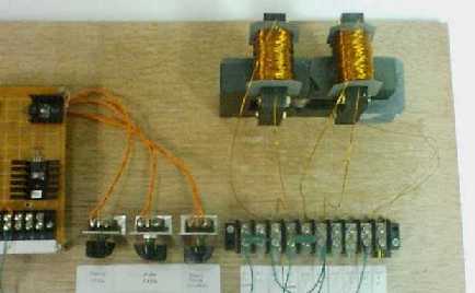
A triple wide core of the same ferrite material is used with new windings. A secondary of 500 turns of #24 is used, with dual primaries of 100/150/200/250 turns. Multiple taps were used for trying different amp/turn investigations. Initial test without magnets, 25 vdc at 24 ma, gives 500 Vpp output into 100 Kohm. Optimum operating frequency is 50 Khz.
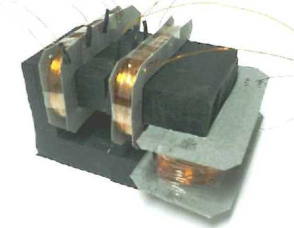
Here are a few pictures of the wider ferrite core and dual
primary windings. 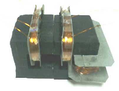