Clear Sky Clock from Reedsburg, about 20 miles southwest from my new observatory.
Quick Links
SSEC infrared image for Wisconsin
Auroral activity over northern hemisphere
| CURRENT
MOON lunar phases |
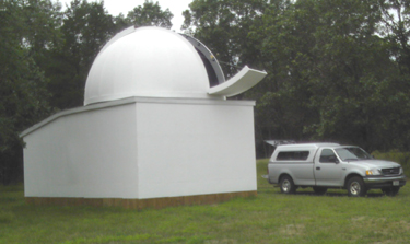
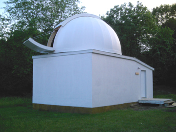
Observatory Construction
My family home is in Milwakee, Wisconsin, and I needed a better dark sky location to set up my 16" scope. Night skies in Milwaukee are poor enough, but street lights and pesky neighbor's yard lights only 30 feet away never let your eyes get night adapted. I have a location in central Wisconsin that I knew had reasonably dark skies, and the milky way is visible every clear night. The nearest town is Wisconsin Dells, about 15 miles to the south. I do see skyglow in that direction, but the heavy oak woods surrounding me block lower angles anyway.
I put in a lot of thought about whether a dome or rolloff was what I preferred to build. A rolloff would be a lot easier to build from scratch, but they don't offer as much winter protection. Cost is a consideration, so prefabricated domes were dismissed. I found enough builders of plywood domes on the web that I knew I could build one for a fraction of the cost of a prefab dome. I made some calculations, and a 16 foot diameter dome would be the minimum I felt comfortable with for my large 16" equatorial scope.
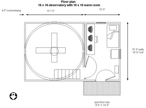
An attached 11 by 15 foot warm room would house computers for CCD imaging and scope control, and have a set of bunks to wait out the nights for morning objects.
Winters in Wisconsin get plenty cold, so a place to take out the chill will greatly add to the utility of the dome in winter.
Here's my proposed floorplan.
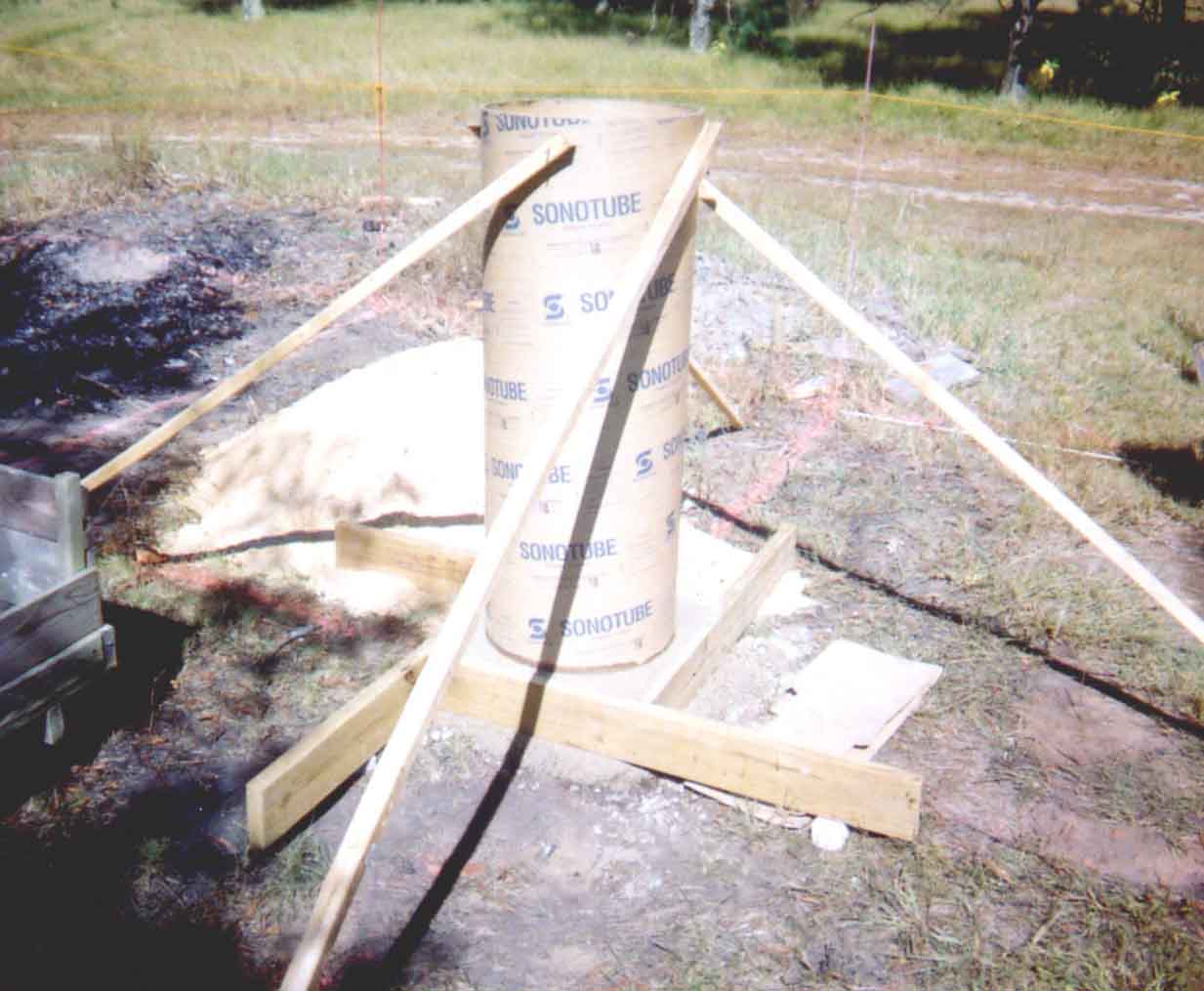
In October of 2004, the concrete pedestal was poured for the observatory. The floor of the dome area is 5 feet higher than the warm room so scope viewing could look over the warm room. Due to the tall oak trees on my property, I can only see down to about 15 degrees in the east and south, and 30 degrees in the west. The extra height of the pedestal above ground added an extra 5 degrees of viewing towards the horizon in all directions. The site of the observatory is about 400 foot from the house, with a finger of woods in between that will block any lights from the house.
A concrete filled hole 4 foot deep and 2 1/2 foot in diameter anchors the pedestal in the ground. Rebar was used in the form to keep it from ever cracking. 35 bags of concrete mix were needed to fill the hole and the 4 foot tall, 18" form. A concrete mixer is a big help here. Four 1/2" anchors bolts were set in the top of the pedestal in a 12" square pattern to anchor a steel pier that will go up through the dome floor.
The plan is to start construction of the building itself in April, 2005. That's about the earliest in the year that the ground will be thawed out for digging foundation post holes. Here's a few sites that I took a lot of inspiration from to build a big plywood dome from scratch.
Mountain Skies Observatory - Dome construction
Pebble Beach - Dome construction and good ideas
Heaven's Glory - Dome construction and scope builder
Cold Spring Obs - Dome with warm room
Building a dome at home
Download a copy of 'At home in a Dome'
List of Observatories constructed by amateurs
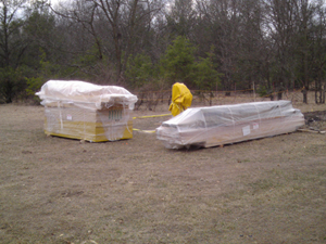
The lumber for the basic building was ordered and delivered to the site the first week of April, just as the frost was coming out of the ground. A couple big stacks of plywood, OSB, posts, studs, joists, and rafters gets me excited that spring is here!
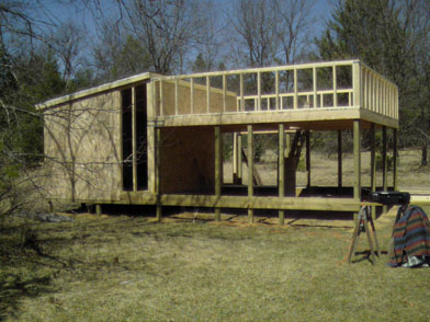
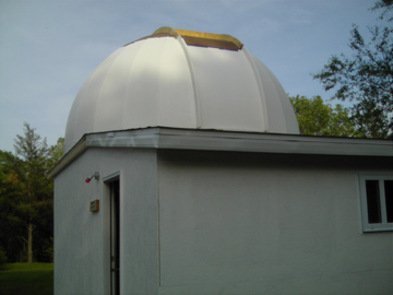
A week later, and 65 pounds of nails and screws later, the building starts to take shape. This is a view looking north, with the warm room on the left. The observing platform is raised to look over the top of the warm room. Normally the warm room is placed on the north side, but in my case the driveway was too close to allow that. The entire structure was built about 18" higher than I originally planned since the land has slight slope to it. The side benefit was a taller storage area under the dome floor that allows my 6'4" height to easily walk around in it. The concrete pier can be seen under the center of the observing platform, but it could have been poured taller. The walls of the observing platform are 37" tall, and will support a roof framework for the dome support ring. The warm room floor is already insulated with R-19 fiberglass insulation, with the wall and roof insulation coming later. Standard stud framing is used for the walls of the observing deck and warm room.
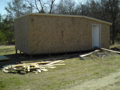
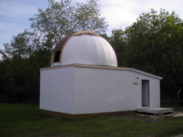
This is a view looking south, with the warm room on the right. Oriented strand board (OSB) sheathing is used to cover the framework. Vinyl siding will be added later to match the house and garage.
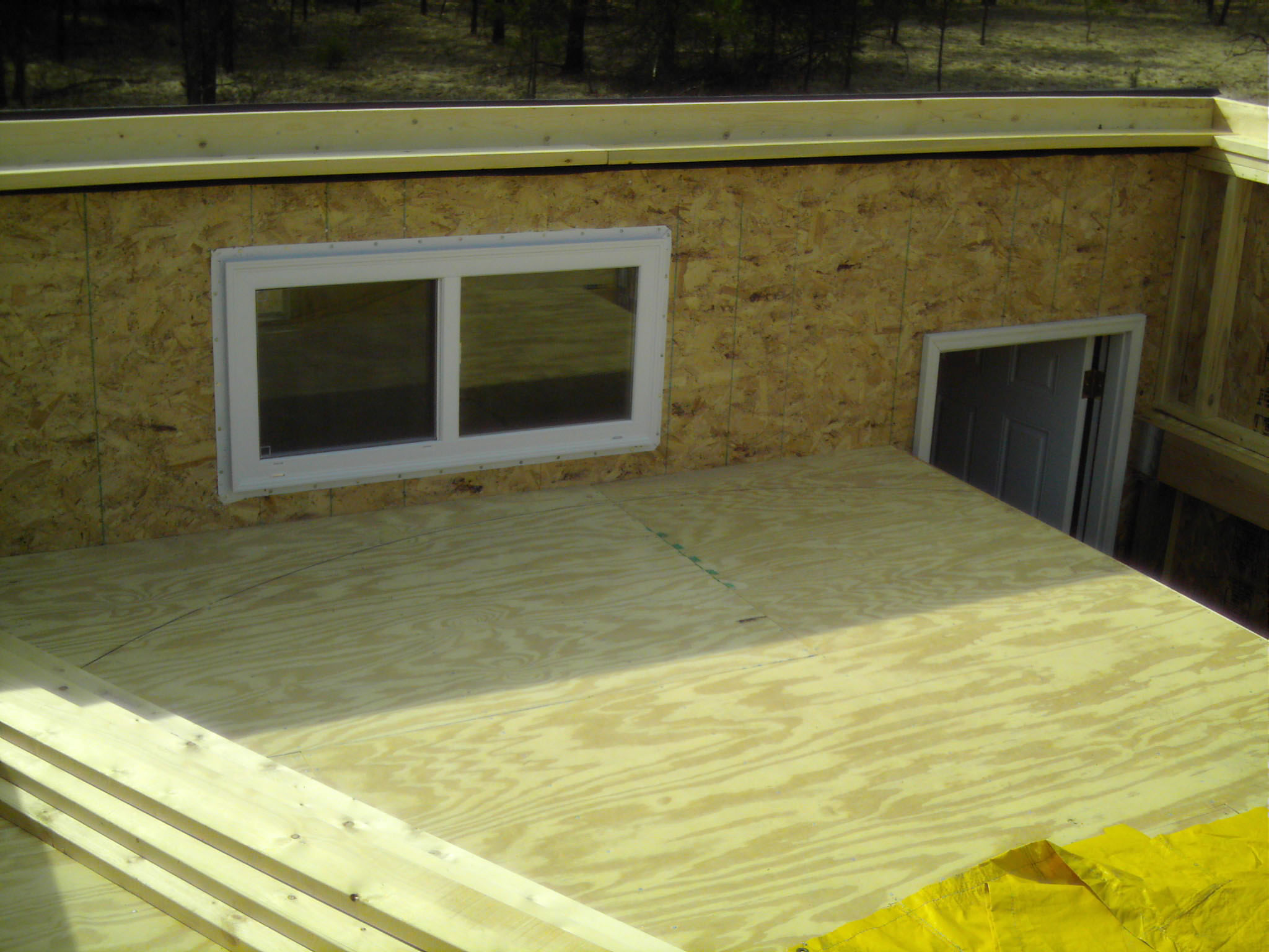
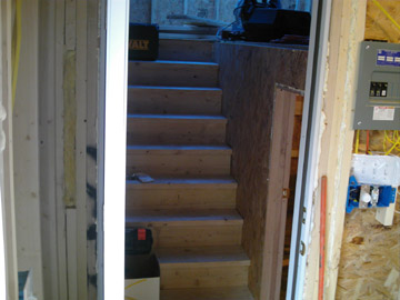
A viewing window between the warm room up to the floor area of the observing deck was installed. The largest viewing window that I could fit between the dome floor and roof line is 24 X 48". It is located above the computer desk of the warm room. The black marker line on the 3/4" plywood floor marks the circular outline for the future dome. The white door at the bottom of the staircase is a full height, 32" wide security door down to the warm room.
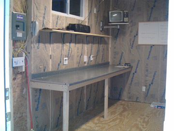
Over the next month, electrical outlets, telephone lines, dimmed lights, and insulation was added to the warm room. A 10 foot kitchen countertop was used for the computer bench.
The stairs are framed from the warm room up to the dome level. A small door at the bottom landing of the stairs leads down a couple more steps to the storage level below the dome room floor.
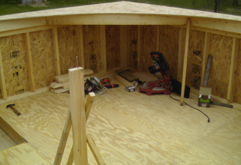
A flat roof framework is added to support the 16 foot diameter dome support ring. The exact center of the square roof was measured, and a nail in the end of the vertical 2x4 is used as the pivot point for the saw's radius arm. The nail reference point is used for all measurements to ensure everything is as circular as I can make them.
Metal flashing is used for roofing material on the flat roof. Sealant is laid down, and a double layer of 3/4" ply, 9 inches wide and 15' 10" OD is used for the base ring. The dome ring is 16' OD and 7 inches wide. A layer of masonite is glued and screwed to the bottom of the first dome ring layer to act as a wheel running surface. The upper 3 layers of the dome ring are added while constantly measuring to the dome center pin reference point. The dome ring is raised an inch at a time and the 16 wheels bolted into place to support the rotating dome ring. Eight temporary side support wheels are added to keep the dome ring centered on the dome rotating wheels.
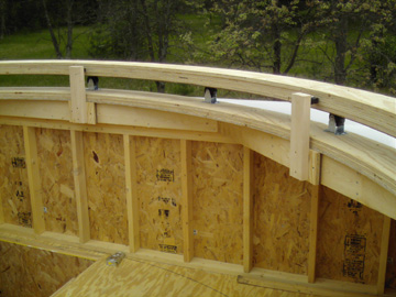
The shutter opening is framed by a pair of half rings. The half rings were built in layers while laying flat on the dome ring and then raised into place with ropes and a helper. The half rings are bolted to the dome ring with brackets, providing for a 4 foot wide shutter opening. The ropes remain in place until the shutter opening is self supporting. The half rings are 2 layers of 9 inch wide, 3/4" ply, and a pair of narrower 4 inch wide layers on inside and outside. These narrower layers are used to give the edge of the masonite gores a solid support on all edges. The shutter frame is 16' 2" in OD, and since it is a chord of the dome ring, it will be be 4 inches above the dome surface to support the shutter tracks.
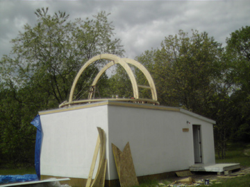
2x4 spacers are added between the shutter half rings and bolted into place with brackets. A 3 layer thick plywood header is added at the top of the shutter opening, 24 inches past the peak to allow viewing directly above. The exact center of the dome peak is found and a temporary 2x4 spacer is added (behind my head in the picture). The exact center of the top of the dome has another nail installed which acts a reference point when adding the dome ribs. All the dome ribs point to this nail reference point. A 48" wide sheet of masonite is screwed to the 2x4 spacers on the rear side of the shutter opening, and this really stiffens up the shutter framework. A temporary 48" wide sheet of masonite is screwed over the shutter opening to further support the shutter rings during rib installation.
Eighteen ribs were preassembled before transporting to the observatory site. They are built up from two layers of 3/4" ply, 16' OD, 4 inches wide. Construction adhesive and screws hold them together. The ribs are approximately 12 foot long when, leaving enough extra length to cut off excess at installation time. Nine ribs are used on both side of the shutter rings. The ribs are spaced 25 inches apart at the dome ring, and are every 15 degrees. Steel brackets are used on both sides of both ends of each rib. The two ribs closest to the shutter opening only have one bracket at the top due to the acute angle. The top end of each rib is marked with the necessary double compound angle, cut close with a sawzall, and final fit to size using a belt sander.
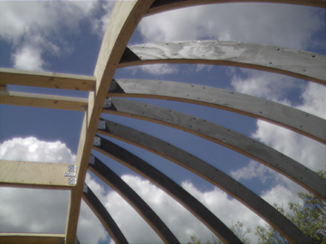
May 30, 2005
A 2x2 backing board is installed 96" up from the bottom of each rib to give a backing at the skin seams. The dome skin is made from 3/16" masonite. Each sheet is placed over the ribs, marked, and cut 3/4" wider with a circular saw. Drywall screws are used to anchor the masonite skin to the ribs. The gores are approximately 25 inches wide at the bottom, and 13 inches wide at the top. One sheet of masonite will make two gores with minimal scrap. As each gore was installed, a bead of caulking is placed in the gap.
May 31, 2005
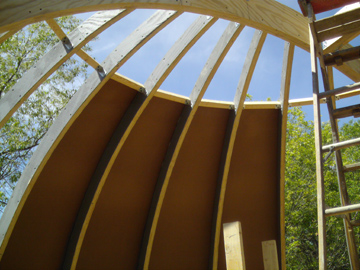
To prevent leakage between gores, a layer of epoxy and fiberglass cloth is added over each seam. On both the base ring and dome ring, overlapping strips of masonite are added, epoxied, and fiberglass clothed. At this point the small gore pieces at the top of the dome haven't been added yet.
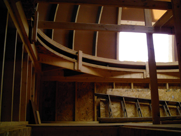
Here's a view looking up into the dome area from the bottom of the short staircase. The shutter opening still has the temporary spacers and covering in place. The vertical 2x4's on the right side of the picture are part a temporary work platform so that less ladder climbing was needed during construction.
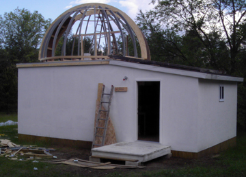
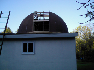
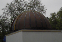
To protect the installed masonite from rain damage until construction can continue, 2 coats of oil based primer was added. When the dome skin was all installed, seams epoxied, and primed, 2 layers of flexible mobile home roofing paint was added.
June 1, 2005
My dome will have an over the top shutter arrangement with a lower shutter that drops down. The upper shutter is fabricated from a double thickness of 3/4" plywood for each side rib. Masonite is used for the skin, with a epoxy and fiberglass coating. The shutter side ribs overlap the shutter frame rings to keep the rain and snow out. A 3" wide aluminum strip is screwed down onto the edge of the shutter frame, and steel garage door wheels roll on that to support the shutter. The lower shutter flips open, and is 5 foot long. Both upper and lower shutters are 55" wide to cover the 48" wide shutter opening. When the lower shutter is flipped up, the upper shutter is slid downward, and metal flashing covers the gap that is between them.
The dome takes a very strong shove to get it rotating. There are 3 seperate motor drives to power each of the shutters and for dome rotation. A 12v battery is mounted inside the rotating dome and powers both of the shutter gearmotors.
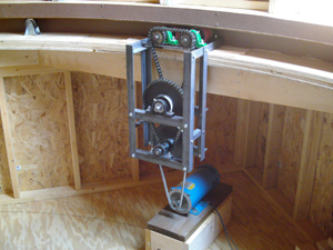
All 16 of the dome rotating ring wheels were replaced with a better quality wheels. I changed from a hard solid caster to a neoprene covered aluminum hub caster. The original casters had delrin sleeves, and the new casters have ball bearings. The force to rotate the dome has decreased, and rotating is much quieter. I had noticed some wear to the masonite surface on the bottom of the dome ring when I used the solid wheels, and the softer neoprene wheels will help prevent further wear. The dome drive reduction was fabricated from 1.5" angle iron, pillow block bearings, 3/4" shafts, and various sprockets and V belt pulleys. The total reduction is 30:1, and with a maximum motor RPM of 1750, the dome rotates all the way around in about 65 seconds. One key feature I designed was using neoprene covered cast iron wheels that fit between the dome and base ring. I wanted to avoid cutting through the base ring to drive the dome with a larger diameter rubber tire. I also wanted to avoid putting any side pressure on the dome with a lateral dome driving wheel. I installed two pair of these drive wheels under the ring, on a pair of drive shafts so I had plenty of driving force. The motor is a 1 HP, DC motor with an electronic speed control. The control has variable accel and decel adjustments so the dome rotating speed is smooth with no sudden starts or stops. The motor horsepower is way overkill with the 30:1 reduction, but it's what I had laying around.
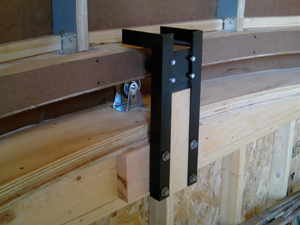
The final dome lateral guide wheels are housed in 4 welded brackets. The guide wheel housings also are the dome hold down brackets in case of heavy winds. 1.5" angle iron and 1/4" steel plate were welded together to make the brackets. The 4" lateral guide wheels bolt to the 1/4" steel plate, and push on a masonite ring attached to the inside edge of the 4 layer thick dome ring.
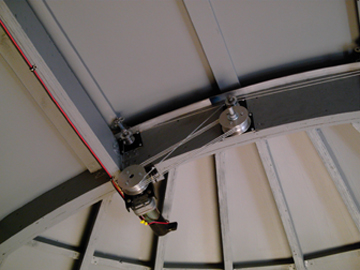
The inside of the dome is painted with a dark gray porch and floor enamel paint. Since the concrete pedestal I pourde alst year was too short, additional rebar and concrete were added to extend it to 4" below the dome floor level. The upper shutter gets a pair of multislot cable pulleys to make a smooth cable drive system. The sheaves are machined from 3.5" diameter aluminum bar stock, with aluminum plates bolted onto both edges to prevent an errant cable from slipping off the side. The primary sheave has 4 grooves machined into it, and is keyed onto the gear motor shaft. The secondary sheave is free spinning on 5/8" spindle and has 3 groves machined into it. There are guide pulleys every couple feet along hte shutter frame to play out one end of the cable, and to catch the other end of the cable as the shutter lip moves past it. Cable tension is maintained by a pair of turnbuckles where the cable attaches to the upper shutter lip.
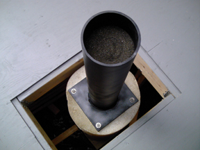
A 6 inch diameter steel pipe is welded to a 12" square, 1 inch thick steel plate, and then bolted to the concrete pedestal. The steel pipe had a noticable ringing to it when struck, which lasted for several seconds. I filled the pipe with 50 pounds of sand blasting sand, and the ringing was completely removed. Sand blasting sand has nearly all the grains the same size, about 80 grit, and won't hold moisture like beach sand. Just make sure to tap the side of the steel tube as the sand is poured in to promote settling.
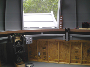
Here's a view of the shutter opening with the shutter motor control pushbutton panel mounted to the right side shutter frame. Both of the shutter gearmotors run on 12 vdc and are powered by a lawn tractor battery mounted to the dome ring. This allows the shutters to be opened or closed while the dome is pointed any direction. Depending on the declination the scope is pointing at, either the upper or lower shutter can be partially closed to block wind.
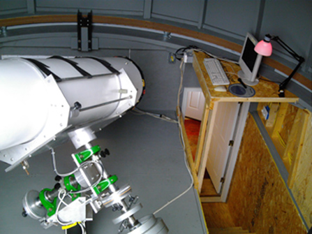
The scope is mounted on the sand filled pedestal. A small bench over the top of the stairs holds a remote set of keyboard/mouse/monitor for the scope drive computer. The computer itself is located in the warm room so it stays warm year round. The monitor is the only thing I need to put away on cold days after a viewing session. When I stay in the warm room and need control of the scope, a seperate keyboard/mouse/monitor are connected to the scope drive computer thru a reverse KVM splitter. Here's a shot of the scope while I was standing up in the shutter opening.
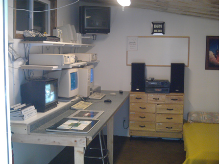
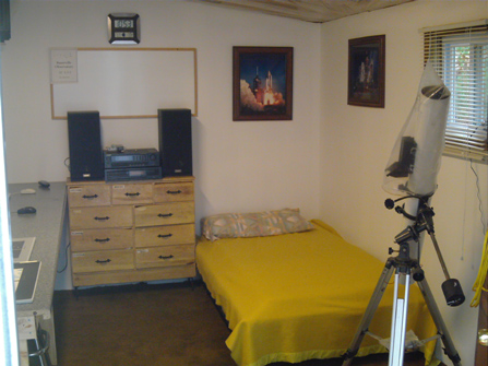
The warm room took quite a bit of time and work to get in shape. The bench was taken back down, and all the walls drywalled and painted. The bench was made wider by placing a sheet of 16" Melanine shelving board behind the countertop. This leaves much more room for the monitors, and leaves work space open for star charts and paperwork. Security cameras were installed around the outside of the observatory and are viewed on a quad video monitor. An old dresser holds tools and spare parts, gloves and hats, office supplies, etc. I originally wanted a set of bunk beds, but I decided on a twin bed so that it could be used for seating area too. Of course, creature comforts are there too, like a stereo and TV. Serveral computers are set up for image capture and processing, internet access, and scope control. The ceiling as yet is still only insulated and plastic covered. The plan is to install a drop ceiling with fiberglass ceiling tiles.
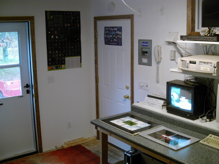
The entry area of the warm room with the outside door, and stairway door to the dome area. Since sleeping in the warm room is an option, I included a smoke alarm and fire extinguisher. A dryer vent is used to allow cables to pass between the floor of the dome area and the computers inside the warm room. After the cables were strung, it is stuffed with a chunk of fiberglass insulation to keep out cold and those darn Chinese beetles.