See construction of Bauerville Observatory
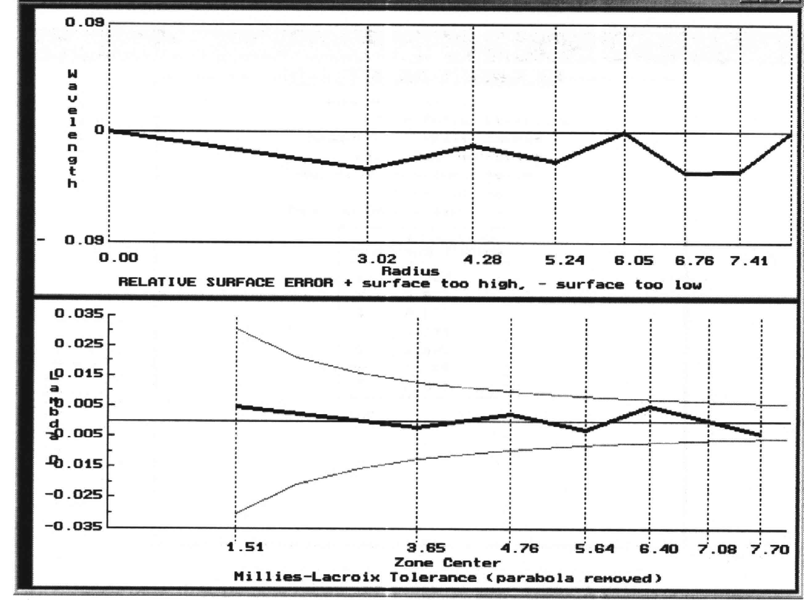
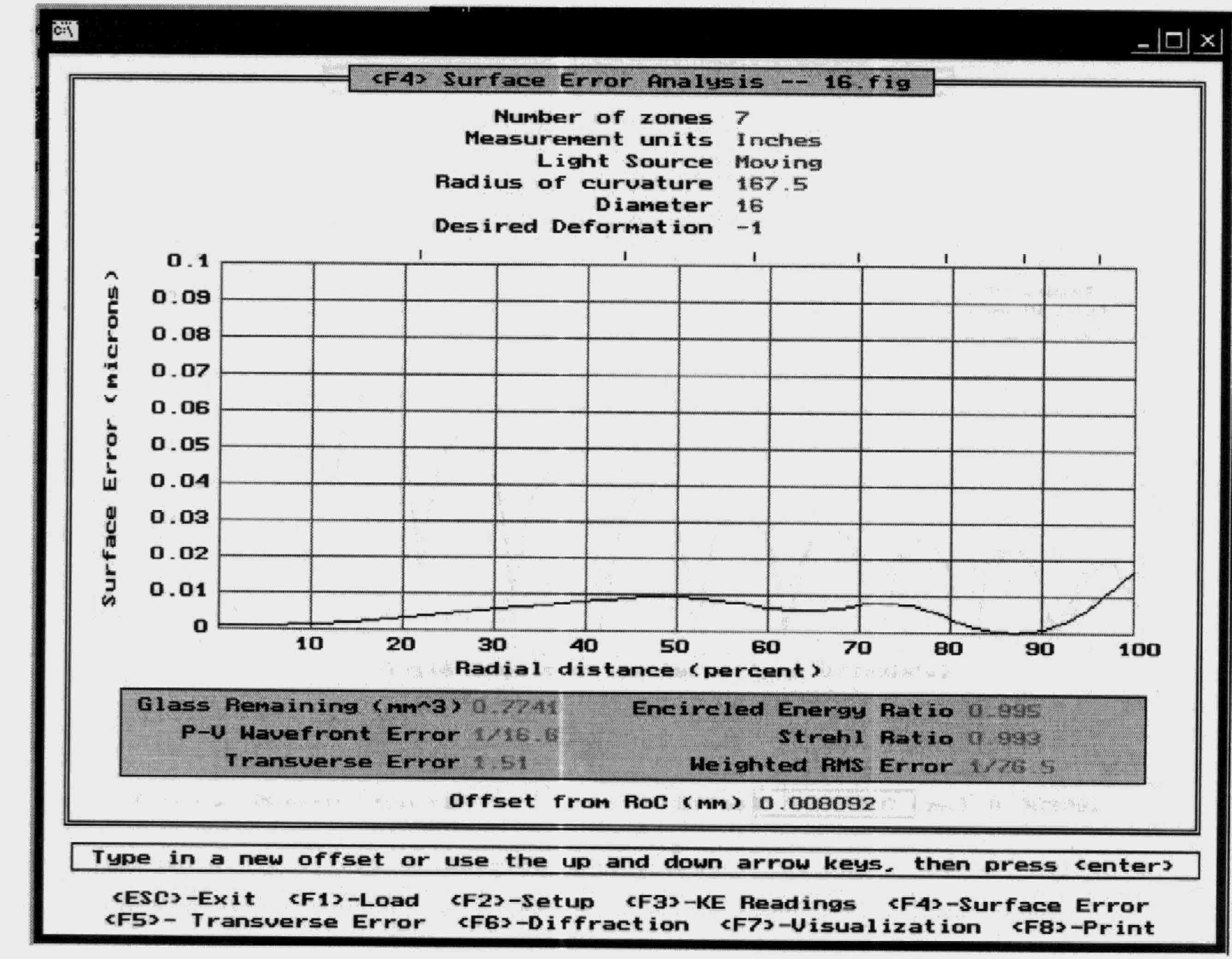
I ordered a mirror blank and grinding kit for a 16" thin mirror from Dan Cassaro back in 2002. It came with all the needed grit sizes, plenty of dental stone to pour several full size tools for making the ceramic tile grinding and polishing tools, and pitch to make several sizes of pitch laps. The blank came pregenerated to F5.2, and when I got it completed, it ended up at F5.24. The whole mirror grinding process was a learning experience, and my mirror log book has a many hours in it. Grinding and polishing only took 26 hours of actually "pushing glass". Figuring and measuring took longer though. This was my first and only mirror so far, so learning on such a large mirror really taught me a lot. A smaller mirror as a first project would have been much easier as the final figuring is tougher on a large thin mirror. A log book is a must to keep from going off on a tangent when refiguring. I built a focault tester and mirror stand to measure my progess. I am very happy with the mirror when I finally got to the point of saying "enough, I want to use it". I used FIGURE45.EXE and TEX.EXE as my analysis programs. The calculated strehl was 0.99, and the MonteCarlo analysis reported an 80% confidence level of 1/10 wave or better. I sent the mirror out for coating to Spectrum Coatings. Make sure to ship it in a plenty strong box. I shipped mine in a wooden box, with the mirror inside wrapped in tissue paper and foam. The wooden box was fitted into a bigger doublethick cardboard box with 2 layers of the pink 2" foam board on all sides. You don't want it damaged after so many hours of work.
I originally purchased a 9 point 16" mirror cell from University Optics, but the support points were simple rubber disks mounted 3 to each single
fixed support arm.
Effectively it was not much better at supporting a 16" thin mirror than a 3 point cell.
I could see mirror droop in the off focus images as a changing astigmatism depending on what quandrant of the sky I was looking at.
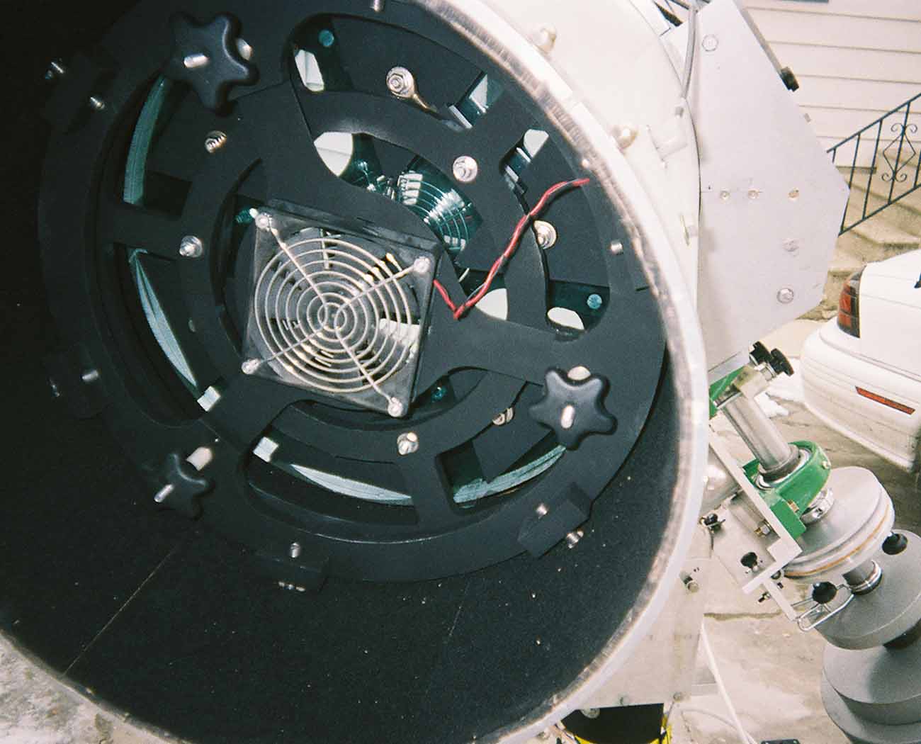
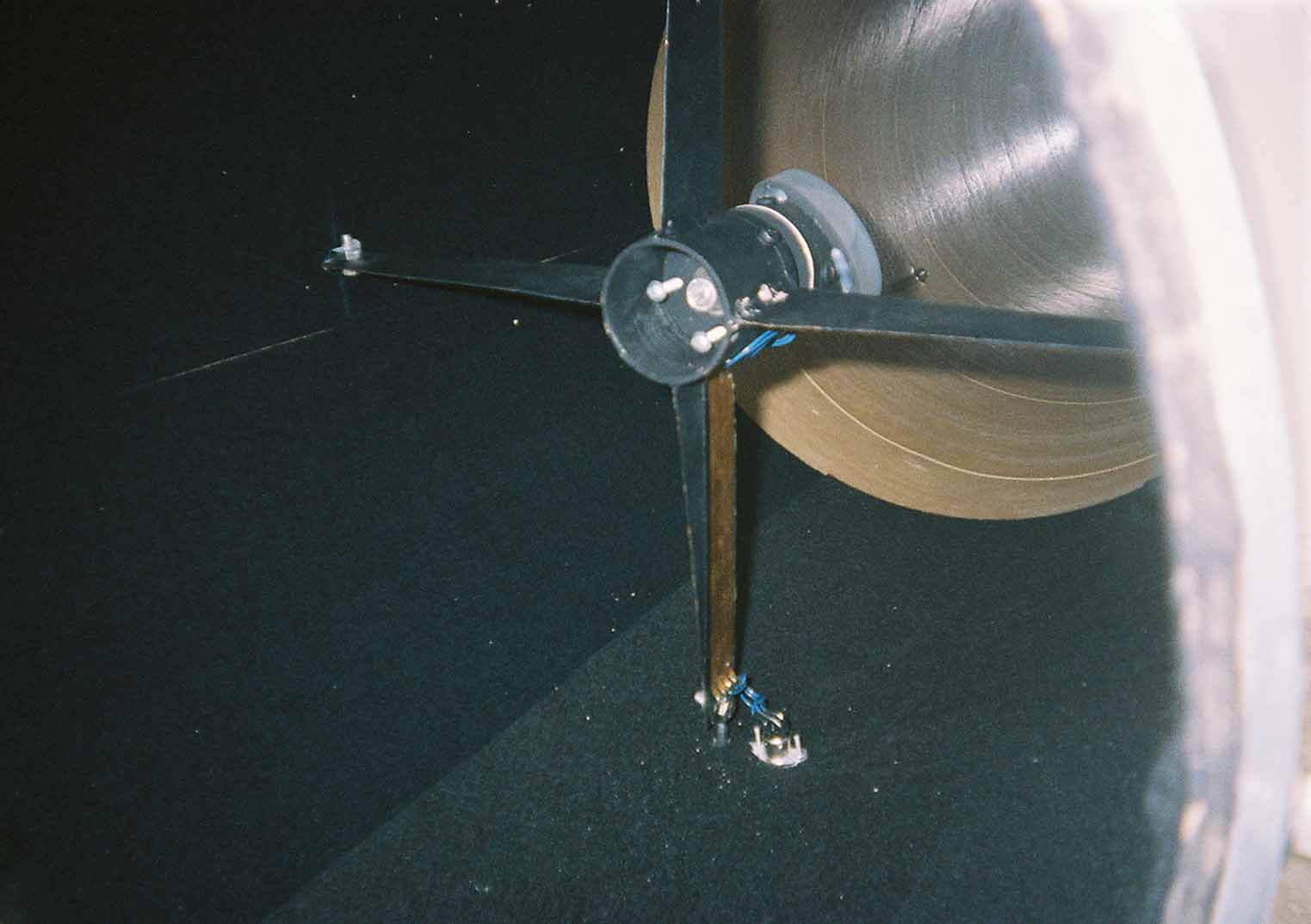
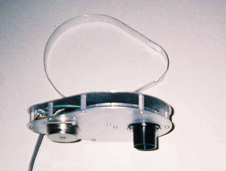
So, a better mirror cell was constructed out of a pair of 1/2" aluminum plates, and is a true 18 point floating cell arrangement.
Much, much better at holding the mirror from flexing in different orientations and holding collimation.
A 12vdc fan halps cool the mirror before an observing session.
I don't normally have it powered on when observing since a slight amount of image vibration is seen at higher powers.
Rubber mounts for the fan would help I'm sure.
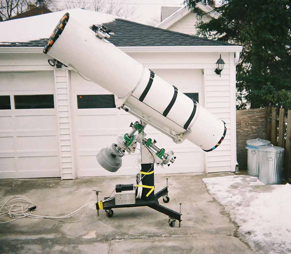
My original equatorial mount (shown below) used 1.5" solid steel shafts with pillow block bearings. The drive system used stepper motors through a pair of 40:1 worm gear boxes on each axis, for a 1600:1 reduction after the stepper motor shaft. This gave a nice step size, but I could never get the backlash reduced to an acceptable level. Large worm gear sets to replace the gear boxes are really expensive, plus the mount I built wasn't suited to retrofit a worm drive. The clutch mechanism I first had was finicky and didn't hold very well. The electronics drive I built was made up of home built circuit boards running of a computer parallel port. I wrote the windows drive software in C++, and though it worked well, it didn't have GOTO capability. I live on a small city lot with neighboring houses 10 feet away, and I had to roll the scope into the garage every night after I used it. Thus I only did rough polar alignments for each use. I welded up support legs onto a 6" steel tube and added wheels and screw anchors to stabilize the mount when being used.
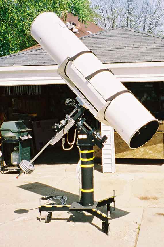
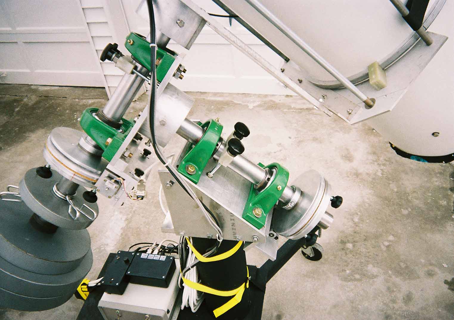
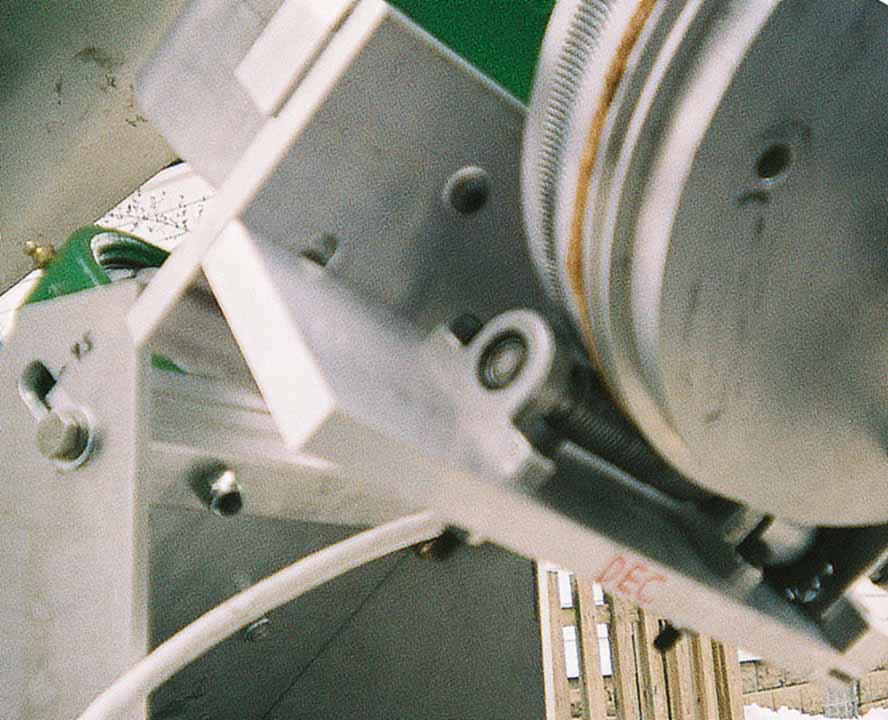
My new equatorial mount is basically totally new everything. The only things I re-used from the original mount was the rolling pedestal and tube cradle. The shafts are made from solid 2" drill rod in larger 2 inch pillow block bearings. I machined new 3/4" diameter worms and 8" diameter worm gears for both axis. The 200 step steppers drive the 360 tooth worms through a 4:1 gear reduction to give a 1440:1 reduction out of the motor. The worm shafts are mounted in small needle bearing pillow blocks and needle thrust bearings. 8" slip clutches are made from 1/2" aluminum plates and use a cork disk as the mating surface. I added shaft clamps so I can lock down either axis from movement. This is really handy when rolling the scope in and out of the garage to protect the worms.
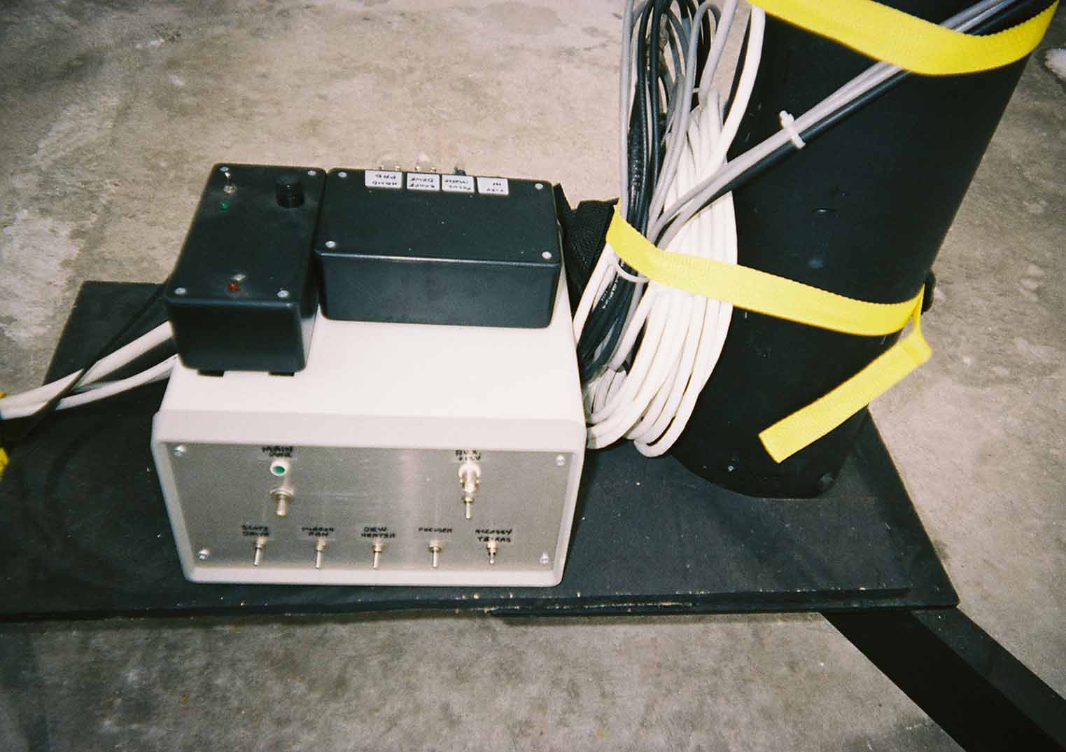
I took the easy route this time and duplicated Bartels electronic circuit and use his excellent software for full GOTO capability. I purchased Guide8 starmapping software that talks with Bartel's scope.exe software for point and click GOTO. I integrated a couple more pushbuttons onto the handpad so I can drive the focuser motor even when the computer is down. The direct wired pushbuttons for the focuser has better response time than the software driven buttons, so I can more accurately focus. The electronics are housed in a aluminum box with 12 volt and 24 volt power supplies. The 24 volt DC supply runs the stepper motors. The 12 volts powers all the telescope acessories and is stepped down to 5volts for the digital electronics. In the picture below, the scope controller box is at the bottom, with switches for each of the 12vdc accessories. The black box on the left is the regulator circuitry for the diagonal dew heater. The black box on the right is the relay control for the focuser motor.
The 18" diameter optical tube is based on a 8 foot lenght section of concrete sonotube. A double wrap of fiberglass cloth and epoxy stabilizes the tube. 1/2" aluminum bar stock end rings keep the tube ends in a fixed circle. The inside is flocked for the first 24 inches from either end with stick-on sheets of black velvety material from a craft store. It would be better to flock the entire inside, but It's hard to reach all the way in. Future project. The optical tube sits in a heavy duty cradle with 1" square bar stock rotating rings. Normally I don't move the optical tube in the rotating rings from neutral since I see an alignment change when I do so. Future project to work on.
The 4 vane spider holds a 3.1" diagonal, and is made up from scrap steel. I added a heater on the backside of the diagonal mirror, and use a temperature sensor to run an electronic regulator to keep the diagonal at 5 degrees above ambient. The heater and controller run off of 12 vdc. I run power in and read temperature out using insulated copper tape stuck onto the spider vanes. This is very slim and there are no wires to block incoming starlight.
The focuser is a factory 2" long travel focuser, modified with a DC motor drive and new knobs. I was getting a lot of eyepiece wobble when I moved in and out so I replaced the factory plastic guide surfaces with adjustable plastic screws. This way I can take up the slop when I see wobble. Converting the plastic guides to ball bearing alignment surfaces would be more work than it would be worth for this focuser. I'll add a whole better focuser onto my TODO list.
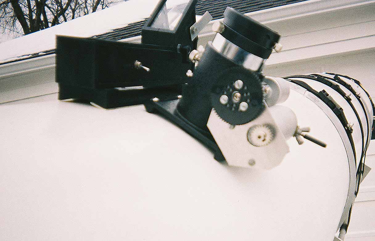
My Telrad is mounted near the focuser. I added a homebrew Telrad flip mirror and window heater circuit that runs off the telescope 12 vdc accessory power. When accessory power isn't available, then the Telrad runs only the LED off an internal 9 volt battery.
My original mount had digital encoder setting circles, but they were directly read by my homebuilt electronics and C++ software. To add them to my new mount, I'll have to convert them to serial output so Bartel's software can read them.
For CCD imaging, I have a SACIV-C and a SAC8 CCD cameras. The SAC8 is much more sensitive than the SACIV-C, and also does long exposures. Though I've had them up both up and running with the driver software, I haven't had much time to learn CCD techniques. The main problem I had was the poor pointing accuracy of my old mount that caused me to much frustration getting an object on the CCD chip.
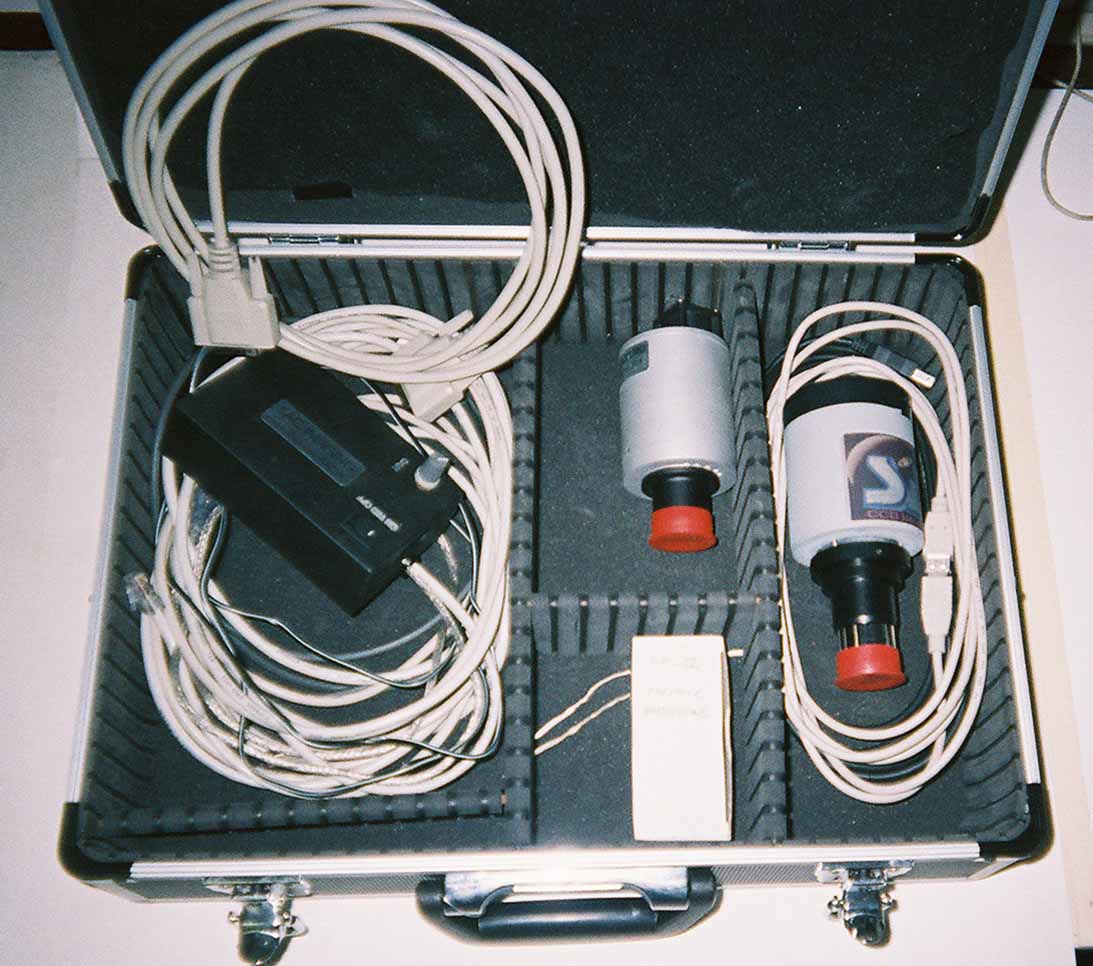
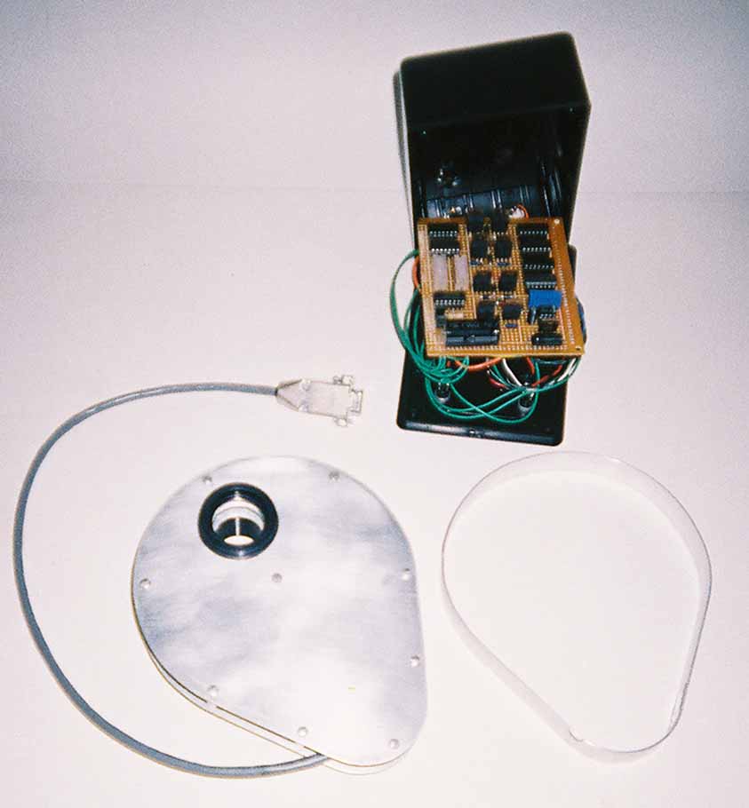
The SAC8 camera has a B/W only CCD, so color filters are needed to create a composite color image. Taking the camera out to screw in new filters didn't allow for keeping an object in correct orientation. I built a 6 color filter wheel using 1 1/4" filters and a stepper motor to rotate the wheel. Of course the controller box is homebuilt and uses optosensors in the filter wheel assembly to detect index holes in the disk to know where it's at. I can use the filter wheel with either the SAC camera or eyepieces.
Building all the telescope components was a 2 year project.
I have a milling machine and metal lathe in my basement, plus drill press, metal bandsaw, and plenty of smaller power tools.
All the steel and aluminum either came from junk yards, or was ordered through a local metal dealer.
The pillow blocks, thrust bearings, shaft collars, special knobs, came from McMaster Carr.
Electronic components were either junk box parts, or ordered from Digikey.
I have full set of electronic test equipment in my ham shack so designing, building, and debugging circuitry was no chore.