
This robot was constructed to compete in the 2005 PDXBot walker competition. The name V8 comes from the robot's lower leg motion which looks much like the piston motion in a V-8 automobile engine.
A rear view shot, showing 4 of V8's 8 legs:
A video of the PDXBot 2005 event (which includes V8 performing in the walking competition) is available from Lemon Studios. On their DVD Josh Triska refers to V8 as a "shuffling robot", and it's an easy mistake to make because V8's legs move very fast, making it difficult to see what's going on in real-time. Playing the video in slow-motion (and pausing/single-stepping) allows V8's gait to be examined (and shows that V8 is picking its feet up off the floor during each step and is not shuffling).
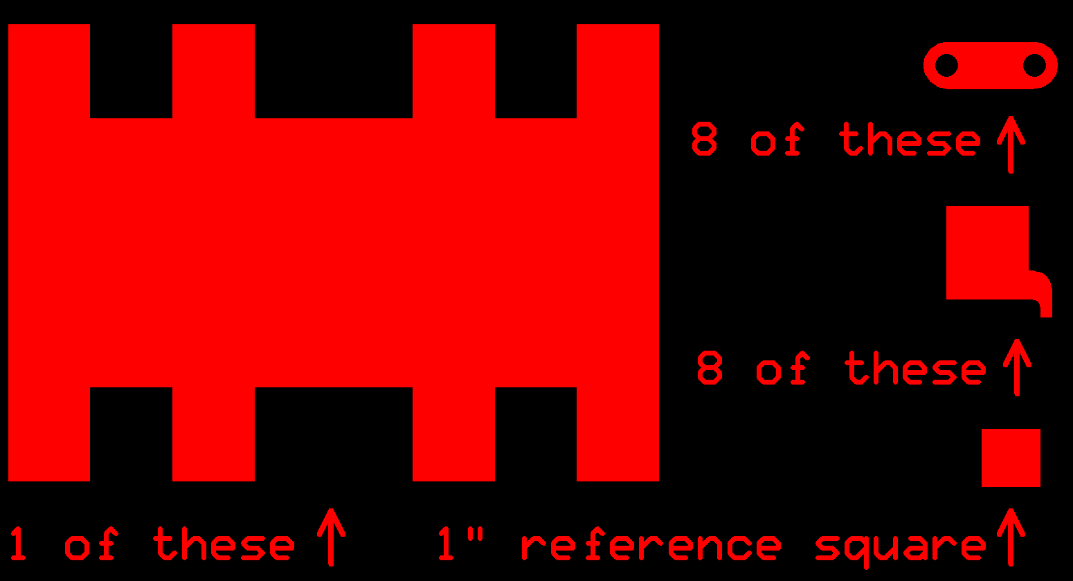
V8 has 8 legs, two legs in each corner of its body. Each leg has two Futaba S3004 servos, one at the "hip" and one at the "knee". The hip-to-knee distance and hip-to-foot distance are 1.5" each (measuring from one axis of rotation to the other, and then to the ground contact point), for 3" total leg length. The servos are load-bearing. (I.e., there is no separate mechanical joint to handle gravity and walking stresses.) The body, servo-to-servo connectors and foot pieces (picture, source) were designed by myself and laser-cut by Pololu. They are made of 1/8" black acrylic. To mount the servo-to-servo connectors, I hand-drilled 192 holes (12 holes * 2 servos per piece * 8 legs) to match the holes on the servo horns and threaded the pieces together with 28 AWG magnet wire coated with red enamel. The rest of the mechanical connections were made using tape (double-sided tape between pieces, and single-sided tape around pieces), and a rubber band to hold the controller board in place.
Some aspects of the mechanical design which may be of interest to other designers:
V8 uses a custom controller board (picture, source), designed by myself and fabricated by ExpressPCB. The power regulator, controller, and servo connectors are the only parts of the board that are currently used during the walking contest. All 16 servo signals are generated using a single Atmel controller (either an ATmega16 or an ATmega32). The robot is powered by a 7.4V, 3.1AH lithium polymer battery.
The controller board has a USART port (J21) that was used in conjunction with a calibration program loaded on the controller board to calibrate the servos. (Sending the same timing signal to two different servos does not result in them going to the same angle. So V8's code has servo-specific adjustments that it applies. Unfortunately the calibration adjustment required by these servos apparently varies with power supply voltage - and the power supply voltage varies depending on how recently the battery has been charged. This results in V8 not walking in a straight line and not walking very smoothly when the battery is nearly fully charged.)
The board is ISP-capable, but the controller is mounted in a ZIF socket (and I have also put a ZIF socket on my STK-500 which I use for programming), so that feature wasn't really needed.
The board also has 8 channels of 12 bit, 100 ksps ADC capability. Several of those channels are connected to a SparkFun inertial sensor (x/y/gyro) daughter-board. However, the sensors on that board turned out to be too inaccurate for use in an inertial navigation system. (I could have determined this ahead of time if I had done the math...)
The board also has a tactile switch and a number of LEDs which were intended to be used to implement a user interface. I never finished that aspect of the software. The primary objective of the user interface was to be able to select the number of steps V8 would take in the turn. (V8 skid-steers like a tank, so the number of steps required depends on the race surface. The amount of required rotation also changes based in whether V8 is going straight when it is supposed to, or is pulling one way or the other.) Instead, I ended up programming several AVRs, each with a different number of steps, and then on the day of the contest I put in the one that worked on the actual race surface.
Some aspects of the board design which may be of interest to other designers:
Here is a partial bill of materials with Digikey part numbers and usage descriptions.
Using the ATmega16 or ATmega32, driving V8's 16 servos is fairly easy and consumes practically no CPU time.
The servo pulse lengths are created with a resolution of 62.5 nsec and worst-case accuracy better than a usec. (The accuracy is not as good as the resolution for two reasons: 1 - Two different interrupts are used to drive the servo signals, 1 interrupt for every 8 servos and, though it rarely happens, these interrupts can interfere with each other's timing. 2 - Different AVR instructions require a different number of cycles, and the controller only launches a triggered interrupt after the current instruction has completed.)
A page describing some of the software techniques used and full source are both available.
V8's walking gate is modeled after the motion of a tank tread, as can be seen in this simulation of two of its legs. (Note: The simulation requires MS Windows 95 or later, and requires DirectX 5 or later. Windows XP has DirectX built-in. Use Alt-F4 to exit the program.)
At low speeds, V8's feet follow that motion fairly well. At high speeds, the servos are being commanded to move faster than they are actually capable of doing, and the feet only come a small distance off of the floor.
As seen in the simulation, the two legs in each corner operate 180 degrees out-of-phase, and during the portion of the step where a leg is off of the ground the leg is commanded to move quicker than during the portion where it is on the ground. This is done so that the leg which was lifted and moved forward is planted back on the ground before the other leg "lifts off". The result is that one of the two legs is in contact with the ground (and supporting V8's weight) at all times. With constant support in all four corners, V8's body is very stable and moves smoothly forward. (This is actually not the case in the video, because V8's batteries were nearly fully charged for the competition which throws off the servo calibration, as discussed in the Electrical section above. Its intended smooth operation was however successfully demonstrated at the first monthly PARTS meeting after the competition.)
V8 walks with a stride length of 1.4" and a time-per-step of 160 msec.
Shortly after the 2005 Robothon event (about 6 months after PDXBot.05), it was suggested that robots be penalized for having too many legs. (I have to wonder, if I had made a winning robot which had three legs and did the cha-cha while whistling dixie, would there then be ongoing efforts to penalize dancing, whistling and having an odd number of legs?)
After some thought, I realized that a gait which alternated between supporting one diagnal and then the other (aka "trotting") would probably be stable enough given a robot that was reasonably well-balanced (center of gravity approximately at the intersection of the two diagnals) and had a fast enough step rate (like V8's) such that any small imbalance is not able to have much effect before the next step causes the diagonals to switch.
Eventually, V8 was used as a test-bed for this idea. Instead of operating 180 degrees out-of-phase, the two legs in each corner were changed to operate in-phase (i.e., as a single leg). The immediate result (without any measuring) was that it didn't change much with respect to speed or stability, except during the start/end of each phase of the walking competition (straight, turn, straight) where V8 moves slower (because it accelerates and decelerates to reduce slipping) there was some "wobbliness". (This could be reduced by using a slightly modified path for the ground contact point during acceleration and deceleration. The modification would be to always move up/forward/down at top-speed, even though the "move back" portion was done with varying speed. This would reduce the potential for instability during acceleration and deceleration to be the same as it is when at top speed, and would require having a dynamic stride length.)
As a side note, after fully charging the battery, V8 started to pull to the right when it is was supposed to be going straight. When it was originally programmed for the walking contest it pulled the other way with a fully charged battery. I suspect whichever servo(s) is responsible for this (the one whose calibration is really bad at high battery voltage) is one of the ones whose phase I reversed in order to switch gaits. I haven't run the batteries down enough yet to see if it will straighten-out like it did before with the walking gait.
At the Dec. 2005 PARTS meeeting I tried to demonstrate V8's new trotting gate. It was successful, up until it unexpectedly tried to go off the other end of the walking course. Though I had changed the number of steps during the turn (in order to compensate for the pull to the right), I had not changed the number of steps for the straight section (which has always been 48). The step timing had also not been changed. (The timing is driven by the mcu's crystal oscillator.) This meant V8 had to be moving further per step (and faster) with the trotting gait than with the walking gate, even though I did not change the commanded servo path (other than the phase change). After the meeting we went out to the garage and measured how far V8 was going with the new gait. (And I used the video recording of PDXBot.05 to determine how far V8 was going with a walking gate.) The results are: